Guide for setting up USBCAN tool & procedure for upgrading firmware (BMS Display and Controller - Gen 3 Only)
Prerequisites:
Computer running Windows OS.
Internet connection for downloading ‘Homegrid Firmware Tools’ containing firmware and software.
USBCAN Toolkit (Available from HomeGrid Support)
- USBCAN tool
- Custom Cable (DB9 to RJ45)
- USB Cable


Visit HomeGrid’s downloads page at https://www.homegridenergy.com/downloads
In the ‘Downloads’ page click on ‘HomeGrid Firmware & Tools‘(Download should automatically start, approximately 480MB).
After the download has been completed, locate the downloaded folder (usually in the ‘Downloads’ folder on your computer) and extract the folder by right-clicking and selecting ‘Extract all…’

By default, files will be extracted to the same location where the downloaded ‘Homegrid Firmware Tools’ folder is at.
Once files have been extracted, open the newly created folder ‘HomeGrid Firmware Tools’.
Select and open the ‘Upgrade Tools’ folder to install the drivers necessary for setting up the USBCAN tool.

Select and open the ‘Drivers’ folder.

Select and open the ‘USBCAN DRIVERS’ folder.

Select and open ‘DRIVER 1’.

Select ‘Next>’ on the Setup screen; select ‘Install’, then ‘Finish’ to complete.


Proceed to install ‘DRIVER 2’ located in the ‘USBCAN DRIVERS’ folder.
Select ‘DRIVER 2’ and select ‘Next>’ to continue.


Select ‘Install’, followed by ‘?(Y)’


When the installation is complete, deselect the checkmark located next to the ‘Run CANTest 2.27’ option.
Click ‘Finish’ to complete.

Installation of ‘DRIVER 2’ is now complete.
Next, navigate to and open the ‘Upgrade Tools’ folder located in the ‘Homegrid Debug Tools’ folder that was extracted in earlier steps.


Now select and open the ‘Controller Upgrade Tool (Gen 3)’ folder followed by the ‘UpgradeTools-en V1.6’ application file.


You should be presented with a window that should look like the screenshot below.

You can now plug the USBCAN tool via USB to your computer.
Connect the DB9 end of the cable to the ‘CAN1’ serial port of the USBCAN tool and connect the ethernet (RJ45) connector to the ‘COM’ port on the BMS Controller.


IMPORTANT: If you are updating firmware for both the BMS Display and BMS Controller, make sure you perform the BMS Display firmware update FIRST if there is one available, then proceed to updating the firmware for the BMS Controller.
Before commencing any firmware update, confirm proper setup and communication with the USBCAN tool by selecting the ‘OpenDevice’ button and verify that the indicator to its right turns green as shown below.

Assuming an update is available for the BMS Display, select the BMS Display driver (‘EMS_V2_firmware_3001_1.1_V1.050-Lithion.bin’ in this example) located in the ‘Firmware’ folder inside the ‘Controller Upgrade Tool (Gen 3)’ folder; Select ‘OK’ to confirm the selection.


Next, you will make the necessary settings changes for the type of firmware that you’re updating. For BMS Display firmware updates, change the ‘Protocol Version’ and ‘Target Board’ drop-down menu options to ‘V2’ and ‘EMS’, then press ‘Start’ to initiate the firmware update of BMS Display.

When the BMS Display firmware update is complete, verify ‘Update Complete’ is shown below before proceeding to the BMS Controller firmware update.

Select the firmware for the BMS Controller by reselecting the folder icon in the ‘Firmware Location’ field to the right.
For this example, we’ve selected ‘V3-Mate-Pro-V30193-15S_2001_3.0-Lithion.bin’, located in the ‘Firmware’ folder inside the ‘Controller Upgrade Tool (Gen 3)’ folder; Select ‘OK’ to confirm the selection.

Before pressing ‘Start’, make the necessary changes to the ‘Protocol Version’ and ‘Target Board’ drop-down menus by selecting ‘V2’ and ‘Master’. Press ‘Start’ to initiate the firmware update of the BMS Controller.

After completion, confirm ‘Update Complete’ on the right-hand side before disconnecting the USBCAN tool.

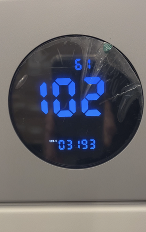
You can verify that firmware has been updated by enabling ‘Firmware Detection’ mode on the BMS. This will put the BMS in a loop sequence displaying the firmware currently installed.
First, you’ll need to change your ‘INV SET’ settings on the BMS Controller. The setting is 101111 or all dipswitches UP except for dipswitch #2 (See image below)

Below are snapshots of firmware currently installed on this stack. BMS Display (101) is showing 01051 (V1.051) and BMS Controller (102) is showing 03193 (V30193). Once verified, you can revert to the original ‘INV SET’ setting you had previously. The update is complete.

Was this article helpful?
That’s Great!
Thank you for your feedback
Sorry! We couldn't be helpful
Thank you for your feedback
Feedback sent
We appreciate your effort and will try to fix the article